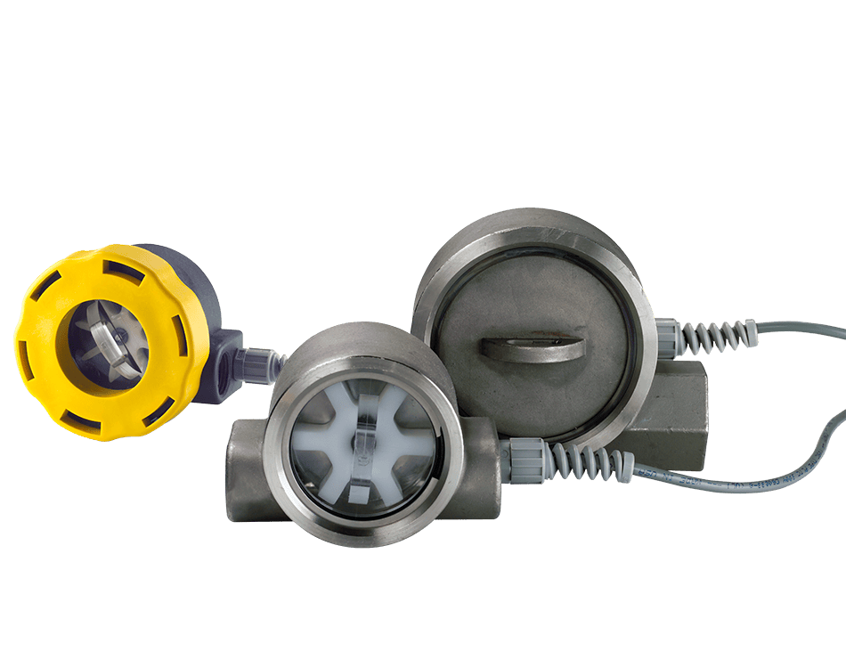
The FlowStat ES Paddle Wheel Flow Meter with integral sensor provides for very simple installation and operation. The economic yet sturdy polypropylene body provides durability at a lower cost. Like its stainless steel cousin, FlowStat ES is offered with multiple outputs to choose from in addition to visual indication of flow through its optional clear cover where you can see the Rotor Flow. The straight fluid path and large spinning rotor means there is minimal pressure drop.
Applications include:
- Chillers & Cooling Systems
- Medical Equipment
- HVAC
- Batching & Industrial Control
| Items |
 VCB-05-B-ES Flowstat ES Turbine Flow Sensor List Price $330.00
|
 CCB-03-B-ES-LF Flowstat ES Turbine Flow Sensor List Price $395.00
|
 CCB-05-B-ES Flowstat ES Turbine Flow Sensor List Price $365.00
|
 CCB-05-E-ES Flowstat ES Turbine Flow Sensor List Price $365.00
|
 CCB-05-V-ES Flowstat ES Turbine Flow Sensor List Price $365.00
|
|||||
| Manufacturer Name | N/A AW-Lake Company | |||||||||
| Type | N/A Flowstat 5GPM Meter | N/A Flowstat 3GPM Meter | N/A Flowstat 5GPM Meter | N/A Flowstat 5GPM Meter | N/A Flowstat 5GPM Meter | |||||
| Style | N/A | |||||||||
| Output | N/A Voltage | N/A Current | N/A Current | N/A Current | N/A Current | |||||
| Port Size Range | N/A 1/2" NPT | |||||||||
| Medium | N/A Fluid | |||||||||
| Measuring Accuracy | N/A 2% of full-scale | |||||||||
| Repeatability | N/A ±0.5% of full-scale | |||||||||
| Flow Measuring Range | N/A 5 gpm | N/A 3 gpm | N/A 5 gpm | N/A 5 gpm | N/A 5 gpm | |||||
| Turn Down Ratio | N/A 10:1 | |||||||||
| Fluid Temperature Range | N/A 20-150°F | |||||||||
| Maximum Operating Pressure | N/A 150 psi | |||||||||
| Filtration Requirements | N/A 150 Micron Filter recommended | |||||||||
| Standard Calibration Fluid | N/A Tap water at 70°F Temperature (21°C), 1.0 sg | |||||||||
| Options | N/A None | N/A Low Flow Adapter | N/A None | N/A None | N/A None | |||||
| Casing Material | N/A Glass-Filled Polypropylene | |||||||||
| Cover Material | N/A Clear polycarbonate | |||||||||
| Seal Material | N/A Buna-N® | N/A Buna-N® | N/A Buna-N® | N/A EPR | N/A FKM | |||||
| Impeller Material | N/A Acetal Copolymer | |||||||||
| Bearing Material | N/A PEEK (Polyetheretherketone) | |||||||||
| Shaft Material | N/A Stainless Steel | |||||||||
| Encapsulant Material | N/A Epoxy | |||||||||
| Strain Relief Material | N/A Nylon | |||||||||
| Lock Ring Material | N/A Glass-Filled Polypropylene | |||||||||
| Wire Insulation Material | N/A High-Temperature PVC | |||||||||
| Power Requirements | N/A 12-24 VDC, Regulated | N/A 12-24 VDC, Regulated, Loop powered | N/A 12-24 VDC, Regulated, Loop powered | N/A 12-24 VDC, Regulated, Loop powered | N/A 12-24 VDC, Regulated, Loop powered | |||||
| Maximum Current | N/A 25 mA DC, Regulated | N/A | N/A | N/A | N/A | |||||
| Load Driving Capacity | N/A | N/A Use the following equation to calculate maximum load resistance: Max Loop Load (Ω) = 50 (Power supply volts – 12). | N/A Use the following equation to calculate maximum load resistance: Max Loop Load (Ω) = 50 (Power supply volts – 12). | N/A Use the following equation to calculate maximum load resistance: Max Loop Load (Ω) = 50 (Power supply volts – 12). | N/A Use the following equation to calculate maximum load resistance: Max Loop Load (Ω) = 50 (Power supply volts – 12). | |||||
| Minimum Load resistance | N/A 1000 Ω | N/A | N/A | N/A | N/A | |||||
| Maximum Transmission Distance | N/A 200 feet recommended | N/A | N/A | N/A | N/A | |||||
| Resolution | N/A Infinite | |||||||||
| Response Time | N/A < 5 seconds to 90% (step change) | N/A 2 seconds to 90% (step change) | N/A 2 seconds to 90% (step change) | N/A 2 seconds to 90% (step change) | N/A 2 seconds to 90% (step change) | |||||
| Over-current limit | N/A | N/A Self limiting at 35 mA | N/A Self limiting at 35 mA | N/A Self limiting at 35 mA | N/A Self limiting at 35 mA | |||||
| Other protection | N/A | N/A Reverse polarity | N/A Reverse polarity | N/A Reverse polarity | N/A Reverse polarity | |||||
| Switch Contact | N/A | |||||||||
| Set Point Repeatability | N/A | |||||||||
| Protection | N/A | |||||||||
| A | N/A 2.06 in | |||||||||
| B | N/A 1.14 in | |||||||||
| C | N/A | |||||||||
| D | N/A 2.48 in | |||||||||
| E | N/A 3.70 in | |||||||||
| F | N/A 3.45 in | |||||||||
| CL | N/A 120 ft | |||||||||
| CL1 | N/A 1.88 in | |||||||||
|
N/A
Value Pricing Encapsulated Circuitry Several Outputs Available Connects Directly to your Flow Monitoring Instruments Simply Plumb and Apply Power |
||||||||||
|
|
||||||||||
